Corrective Action:
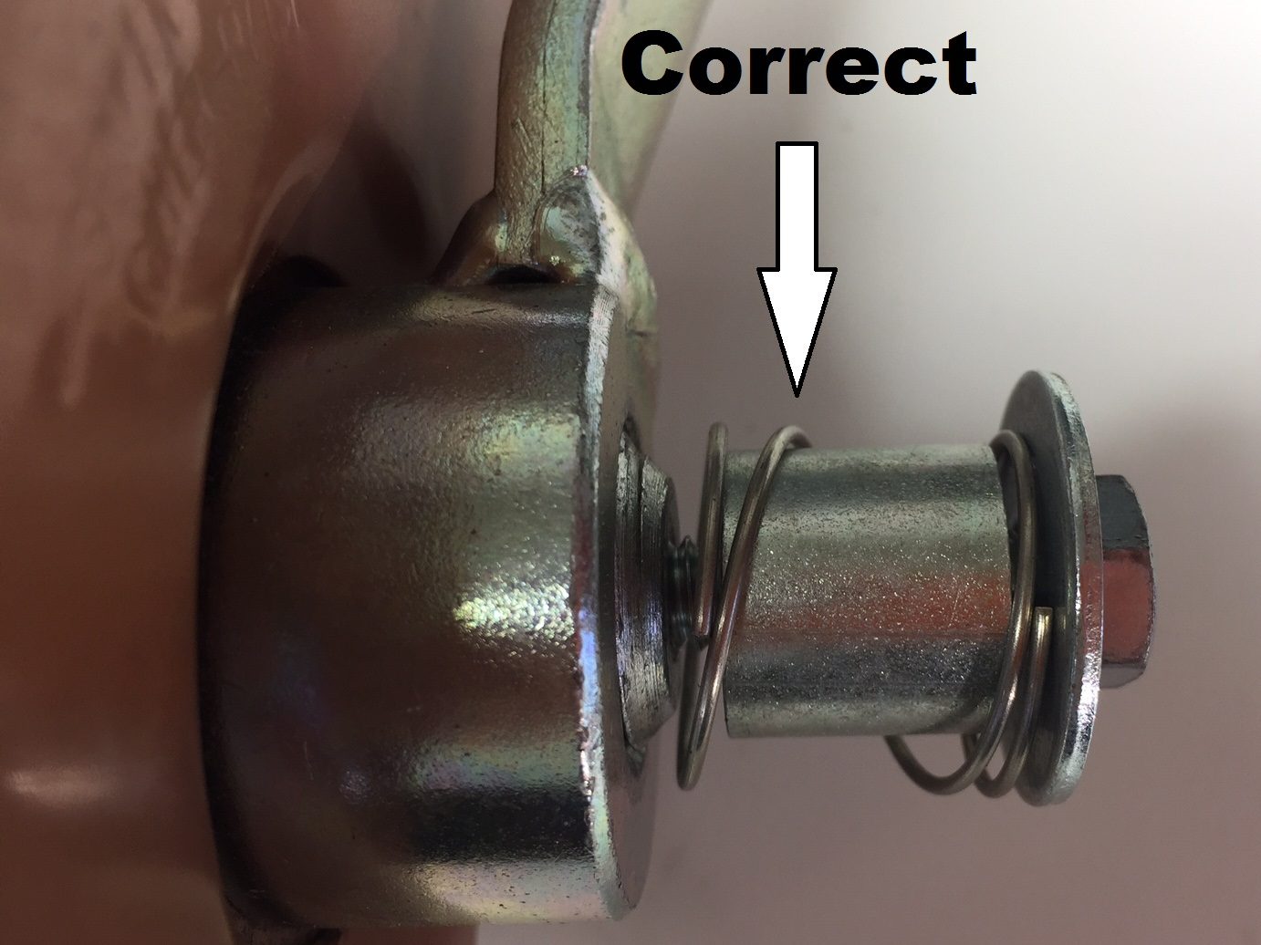
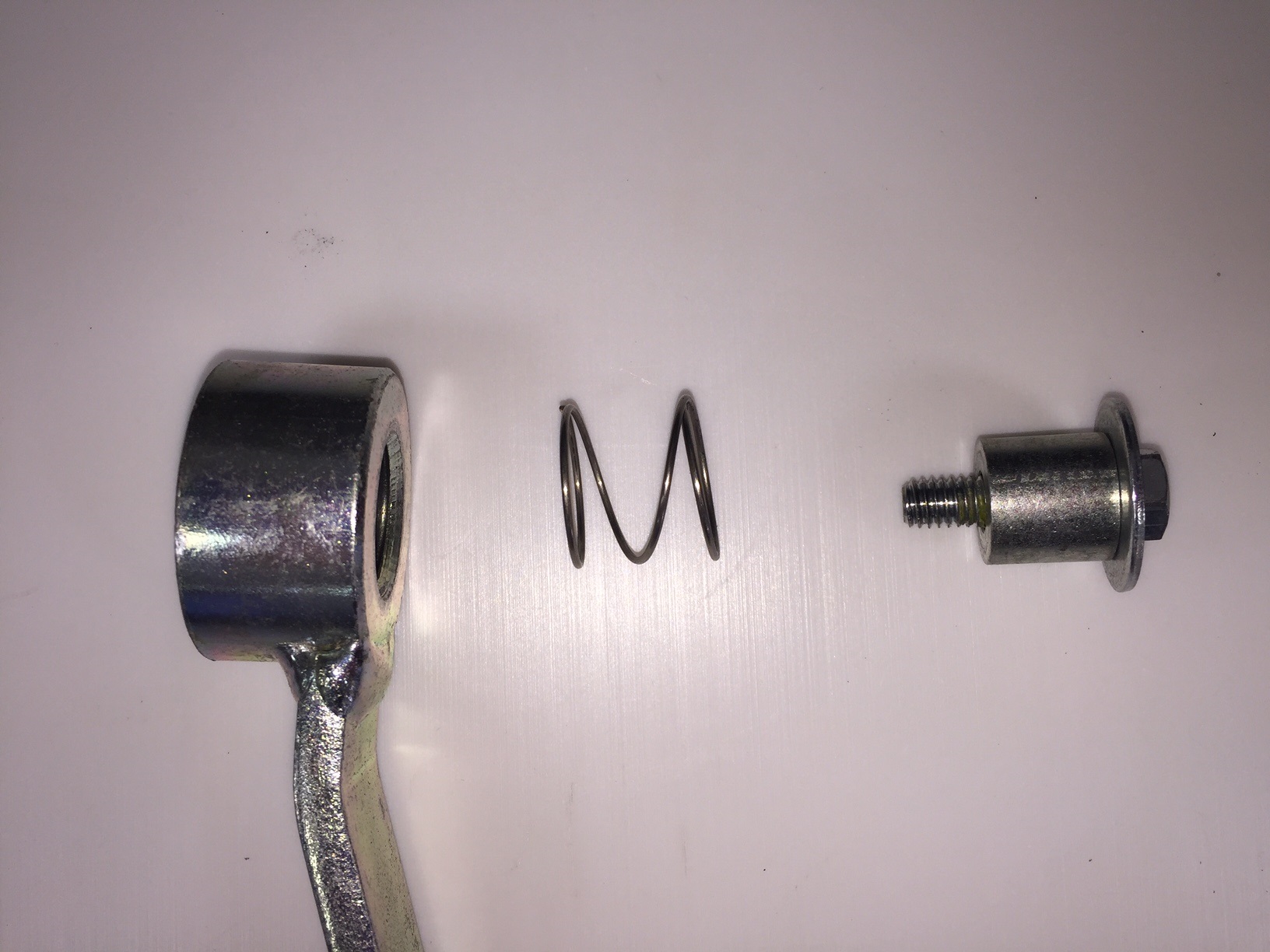
The spring that is intended to go onto the end of the drive shaft may have been placed onto the shaft before the handle was threaded onto the winch. The spring, spacer and flat washer must be in place on the end of the drive shaft exactly as shown in photo. If spring is not present in this location, it was probably placed on shaft before the handle was installed. Remove the bolt, spacer and washer from the end of the shaft and remove handle form shaft. If you now find the spring on the shaft it will likely be severely damaged and will need to be replaced. Order spring P/N 204212. Reassemble parts in the correct order as shown in the photo and the winch should work fine.
Corrective Action:
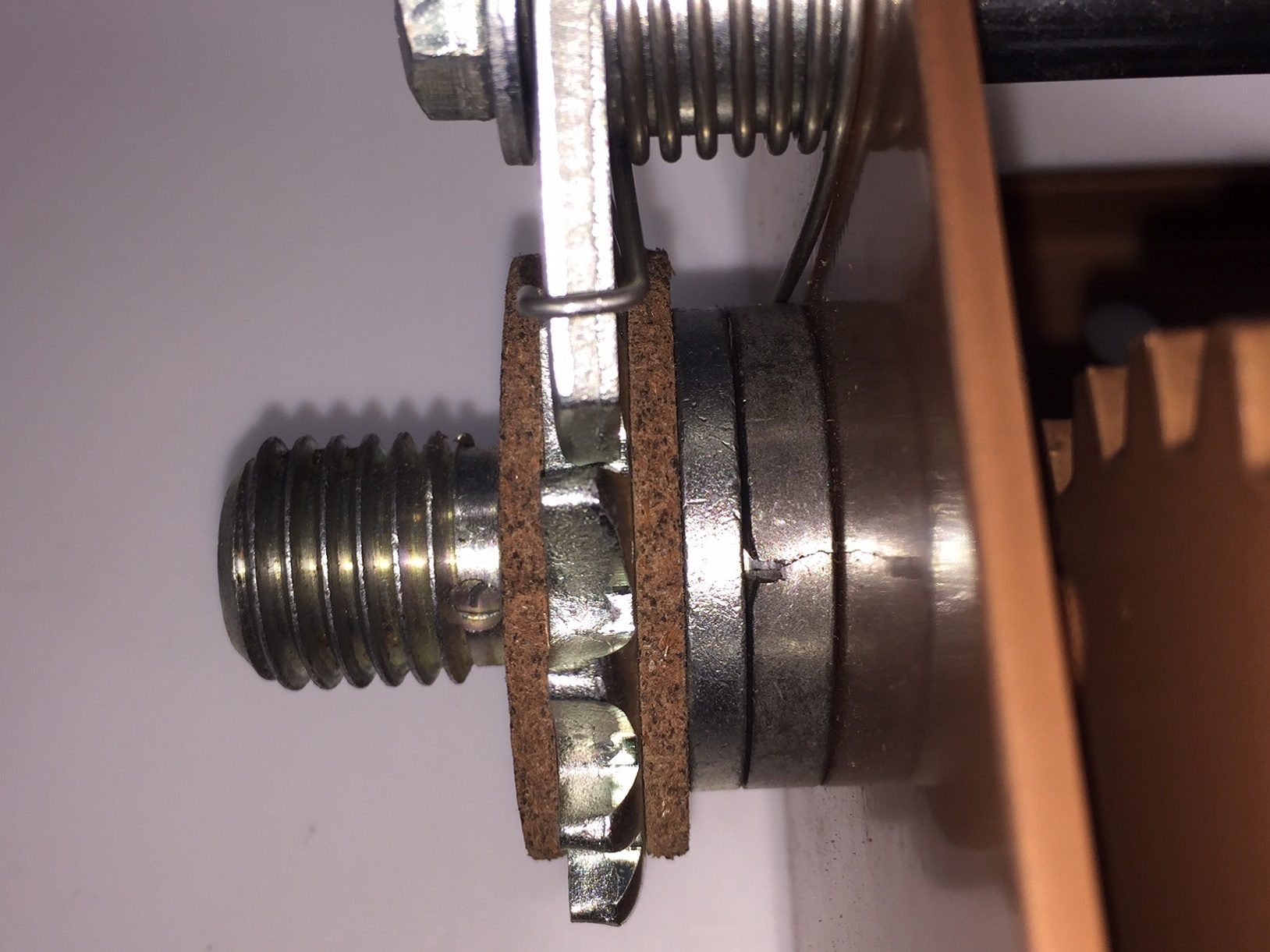
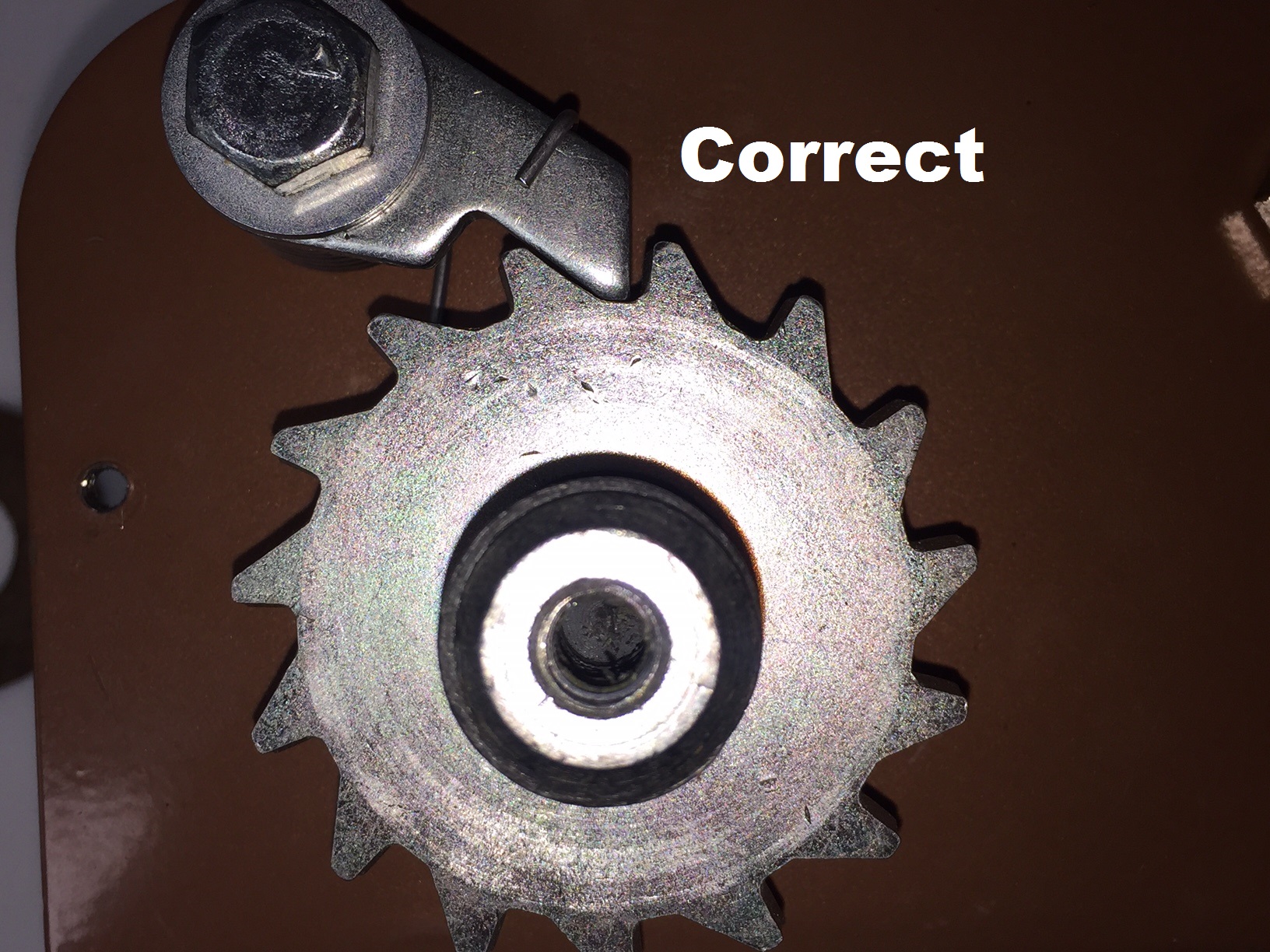
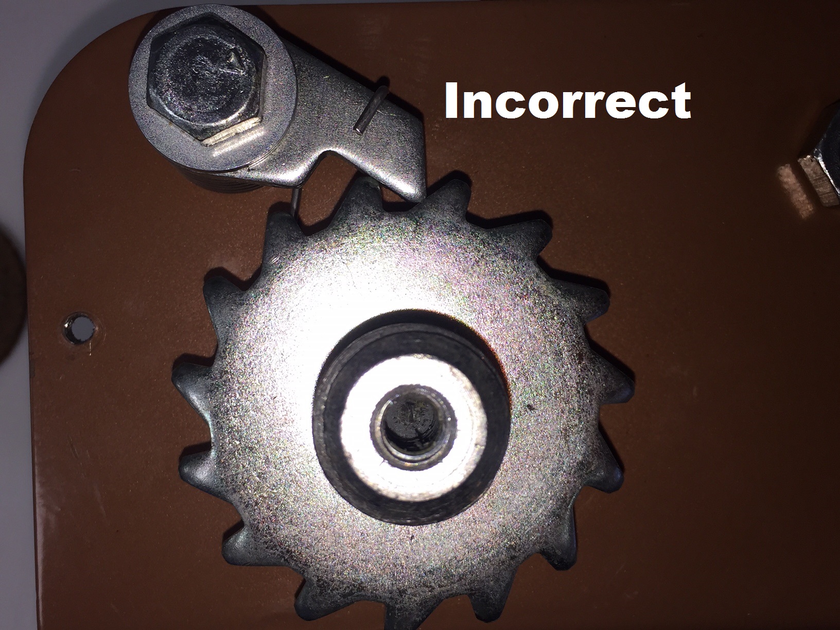
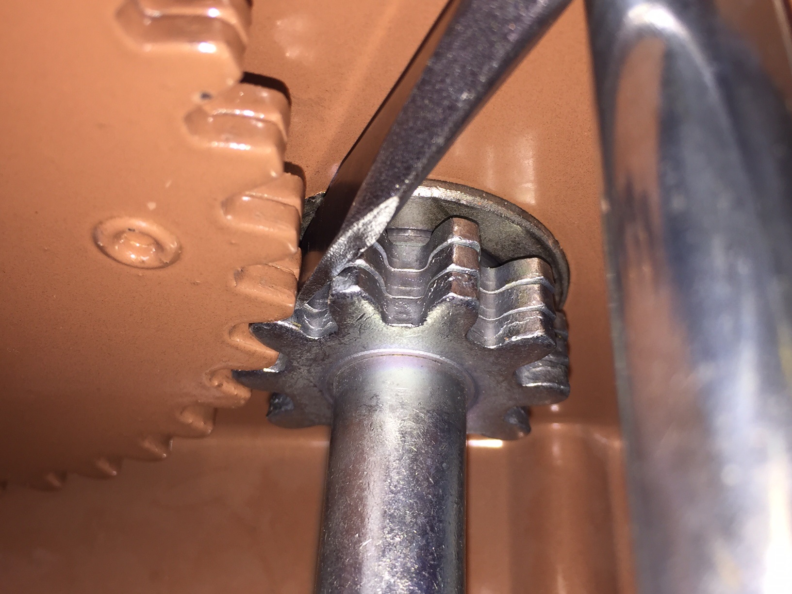
When the crank handle is turned clockwise the winch should produce a loud sharp clicking noise. If the clicking is very soft, then the ratchet wheel may be assembled backwards. Remove the gear cover from the winch by first removing the parts from the end of the drive shaft and removing the crank handle. Confirm that the ratchet wheel is assembled on the shaft exactly as shown in the photo. If the wheel is on the shaft backwards, lift the ratchet pawl up so that it is not touching the wheel and then slide the wheel and outer brake pad off of the shaft. Turn the wheel the correct direction and reinstall it and the outer brake pad onto the shaft. You may wish to install the handle on the shaft and confirm that the winch functions properly before reassembling the gear cover and drive shaft parts.
Corrective Action:
Remove the gear cover from the winch by first removing the parts from the end of the drive shaft and removing the crank handle. Examine the ratchet pawl and spring, and the bolt and spacer that hold the pawl in place. The pawl should have significant spring pressure keeping it engaged with the teeth of the ratchet wheel. Also examine the tip of the ratchet pawl and the teeth of the ratchet wheel, neither should show any significant wear. Confirm that a brake pad is present on both sides of the ratchet wheel and that the pads do not show any obvious damage. Thread the handle back onto the drive shaft. The pawl should be aligned with the ratchet wheel so that it cannot be forced off to one side of the wheel. Turn the crank handle clockwise and observe the action of the pawl. It should click into each of the ratchet wheel teeth with no binding or hesitation. A broken spring or pawl, a bent ratchet support bolt or the pawl seized onto the ratchet spacer should be obvious if they exist. Obtain and install the necessary repair parts. If the spring is simply disengaged from the pawl or the pawl is disengaged from the wheel, reassemble these parts into their proper positions as follows. Remove the handle from the winch. Grip the ratchet wheel and both brake pressure plates as a group and slide them toward the end of the drive shaft. Rotate the ratchet spring counter clockwise until the long end catches against the drive shaft bearing. Then rotate the pawl counterclockwise so that the hook end of the spring catches it and then continue to rotate approximately one half turn more. Hold in this position and slide the ratchet wheel and brake plates back into position against the large washer on the shaft. Release the pawl allowing it to snap into engagement with the wheel. Reinstall the crank handle and confirm that the winch functions properly before reassembling the gear cover and drive shaft parts.
Corrective Action:
It may be that the handle hub is seized onto the drive shaft thread by rust or corrosion so that it can not supply enough force on the brake pads and ratchet wheel to lock the winch. After removing the load from the winch, the handle (or wheel) should be able to be turned very easily on the drive shaft thread. This is designed to be a loose fitting thread. If there is any resistance to free movement, disassemble the parts on the end of the shaft so that the handle can be removed and then investigate the cause of the tightness. Note that if your winch uses a wheel in place of the standard crank handle, the threaded hub of the wheel is often not manufactured by Dutton-Lainson Company and may have been manufactured to tighter dimensions so that the threads do not move as freely as they should. Wheels are also sometimes manufactured with aluminum hubs instead of the steel hubs used on the standard handles. The aluminum threads can be more easily damaged and can be the reason the threads are not moving freely. After insuring that the handle hub threads move freely on the drive shaft thread, apply a small amount of grease on the thread and reassemble the winch.
Corrective Action:
Some manufacturers of crank wheels use a hub that does not have a counter bore in the side that contacts the outer brake pad of the winch. This makes it possible that the hub is contacting the shoulder of the drive shaft preventing the hub from properly tightening against the brake pad locking the brake mechanism in the winch. If you find this to be the case, replace the wheel with a standard crank handle (P/N 5703509) until you can obtain a wheel with a properly machined hub from the manufacturer of your lift.
Corrective Action:
When the crank handle is turned clockwise the winch should produce a loud sharp clicking noise. If this clicking noise can not be heard, then investigate the following possible causes. Remove the gear cover from the winch. This can be done with the standard crank handle on the winch , but if you have a crank wheel, the wheel will need to be removed to remove the gear cover. Examine the ratchet pawl and spring, and the bolt and spacer that hold the pawl in place. Also examine the tip of the ratchet pawl and the teeth of the ratchet wheel. Neither should show any significant wear. The pawl should have significant spring pressure keeping it engaged with the teeth of the ratchet wheel. Make certain that a brake pad is present on both sides of the ratchet wheel. The pawl should be aligned with the ratchet wheel so that it cannot slip or be forced off to one side of the wheel. Make certain that the teeth on the ratchet wheel are oriented as shown in the photo. If the teeth are backwards from the orientation in the photo, this would be the problem. Turn the crank handle clockwise and observe the action of the pawl. It should click into each of the ratchet wheel teeth with no binding or hesitation. A broken spring or pawl, a missing brake pad, a bent ratchet support bolt or the pawl seized onto the ratchet spacer should be obvious if they exist. Obtain and install the necessary repair parts. If the spring is simply disengaged from the pawl or the pawl is disengaged from the wheel, reassemble these parts into their proper positions as follows. Remove the handle from the winch. Grip the ratchet wheel and both brake pressure plates as a group and slide them toward the end of the drive shaft. Rotate the ratchet spring counterclockwise until the long end catches against the drive shaft bearing. Then rotate the pawl counterclockwise so that the hook end of the spring catches it and then continue to rotate approximately one half turn more. Hold in this position and slide the ratchet wheel and brake plates back into position against the large washer on the shaft. Release the pawl allowing it to snap into engagement with the wheel. Reinstall the crank handle and confirm that the winch functions properly before reassembling the gear cover and drive shaft parts.
Corrective Action:
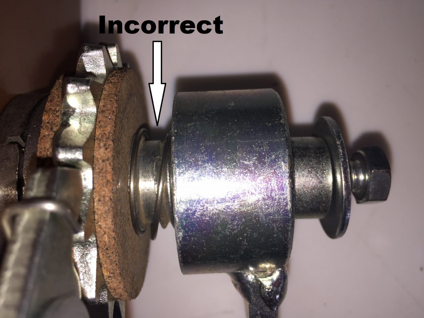
It is not unusual for boat lift manufacturers to alter the components that secure the handle or crank wheel onto the winch drive shaft. This is especially true if the crank wheel hub is made longer than the hub used on the standard crank handle. This often creates the potential for the handle or wheel to get jammed onto the shaft so that the brake is not engaged. Examine the photo showing the standard assembly of components on the end of the shaft. If the spring and spacer are not present, the potential for a jam exists. When the handle(or wheel) is turned clockwise, space must be present between the outer face of the hub and the retaining washer on the shaft. If space is not present here, the parts are jammed preventing engagement of the brake. Loosen the bolt on the end of the shaft and then turn the handle clockwise to engage the brake. Then re-tighten the bolt making sure that space remains between the face of the hub and the retaining washer.
Corrective Action:
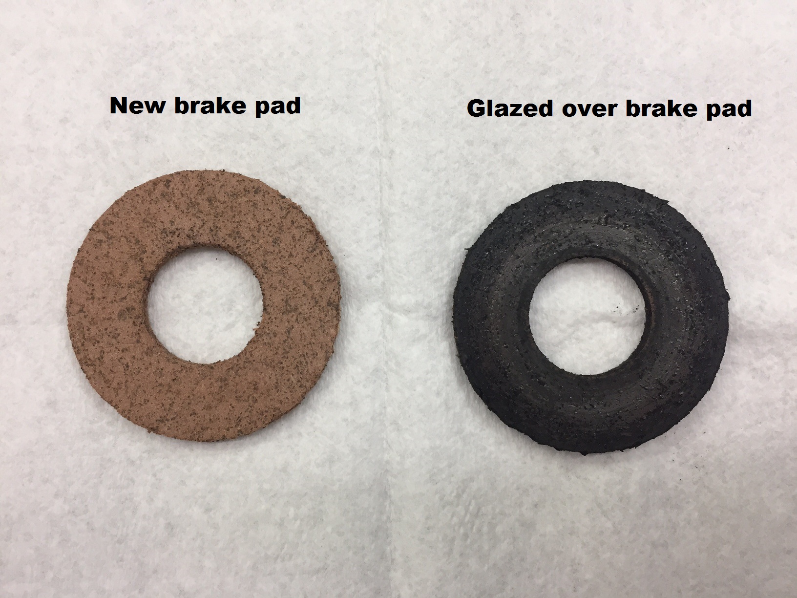
Some manufacturers of crank wheels use a hub that does not have a counter bore in the side that contacts the outer brake pad of the winch. This makes it possible that the hub is contacting the shoulder of the drive shaft preventing the hub from tightening against the brake pad locking the brake mechanism in the winch. This might also be caused by a broken or crushed brake pad. If you find a broken or crushed brake pad, replacing the pads (P/N 205123) should solve the problem. It would also be desirable to obtain a new crank wheel with a properly machined hub from the manufacturer of your lift. A counter bore in the face of the hub will allow the hub to contact the brake parts even if one of the pads gets broken.
Corrective Action:
It is not unusual for boat lift manufacturers to alter the components that secure the handle or crank wheel onto the winch drive shaft. This is especially true if the crank wheel hub is made longer than the hub used on the standard crank handle. This often creates the potential for a load to be raised by turning the handle in the counterclockwise direction. Doing this does not engage the brake mechanism and the winch will not hold the load in place. The handle must be turned in the clockwise direction to raise a load. Examine the photo showing the standard assembly of components on the end of the shaft. If the spring and spacer are not present, the potential exists for raising a load in the wrong direction. If this has occurred, wind all of the line off of the winch by cranking clockwise. Loosen the bolt on the end of the shaft and continue to turn the handle clockwise to engage the brake. You should begin to hear a clicking noise from the brake. Retighten the bolt making sure that space remains between the face of the hub and the retaining washer. Space must be present between the outer face of the hub and the retaining washer on the shaft in order for the winch to work properly.
Corrective Action:
The locknut on the drive shaft on the side of the winch opposite the crank handle may have been over tightened. When there is no load on the winch the drive shaft should be able to move back and forth a slight amount. In other words there should be a slight amount of space between the washer next to the locknut and the bearing in the winch base. On the models B2500 and B3500 there are two shafts with locknuts on them. Both shafts should have the space described above. If this space does not exist so that the shaft can not slide back and forth slightly, loosen the nut or nuts to get a slight space. These are locknuts, so they should stay where you put them.
Corrective Action:
Examine winch frame for any bend or distortion that could cause binding of drive shaft(s) and bearings. Unfortunately, if the frame of the winch is bent, it generally can not be easily repaired and the winch must be replaced.
Corrective Action:
Remove any load from the winch. In this condition the gears, drive shaft(s) and reel should all have a little bit of looseness. It may be helpful to remove the gear cover from the winch. Then check each of the major components to see if it is able to be moved with your fingers. Drive shafts and the reel should be able to move slightly back and forth and side to side. If any of the components can not be moved, investigate further to find and correct the source of the bind. When moving the reel, make sure that the long bolt through the center of the reel remains stationary. If the reel bolt moves with the reel, then the bolt is probably seized in the reel hub. Disassemble, which may require driving the bolt out with hammer and punch, and determine the extent of damage. Also examine the reel bolt holes in the winch frame for any damage. If the holes are noticeably elongated from the bolt turning in the frame, the best course of action will be to replace the winch.
Corrective Action:
Models B1500, B2500, and B3500 use needle bearings on the high-load area (gear side) of the winch shaft(s). Although rare, bearings could fail if the winch is used in harsh environments. The driveshaft(s) should have some looseness and be able to move side to side slightly. If there is an excess in side to side movement in any of these shafts, the needle bearings may have failed and will need to be replaced. To check this, the winch will need to be completely disassembled. Individual needles that are missing and have fallen out of the bearing indicate a bearing failure. These bearing are press fit into the bearing housing in the winch frame. On model B1500 there are two bearings used, one on the main driveshaft and one for the gear being driven by the main driveshaft. Both of these bearing housings are welded to the frame. A hammer and punch are required to get the bearing out of the housing. This will destroy the bearing; however since it is being replaced it doesn’t matter. Since the winch is disassembled you can use a vise to press the new bearing into the bearing housing. Order bearing P/N 205131 for the main shaft and bearing P/N 205130 ( large 1 bearing) for drive gear shaft. On model B2500 models the bearing housing for both the primary shaft and the secondary shaft are not welded to the main frame, so to replace a bearing simply order both the housing and bearings as they will come already pressed together. Order part P/N 404479 for the primary shaft housing and part P/N 205183 for the bearing. If the large 1 bearing ( P/N 205133) in the main frame need to be replaced, it will have to be removed with a hammer and punch in the same matter as mentioned as above on B1500 models. There is also a needle bearing (P/N 205134) used in the gear positioned between the primary and secondary driveshaft’s. If this bearing needs to be replaced it will have to be pushed out and a new bearing pressed back into the gear. Model B3500 is much the same as the B2500, both primary and secondary driveshaft’s use the same bearings (P/N 205183) and the same bearing housing (P/N 404476).
Corrective Action:
Confirm the load on the winch is within the capacity of the winch, refer to owners manual.
Corrective Action:
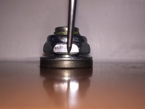
This is fairly rare, but can occur after a long period without use. If there is a load on the winch, a secondary lifting or holding device such as; another winch, forklift, scaffolding, or other similar device, MUST be brought in to remove the load from the winch and avoid the risk of an accident. Once the load has been removed from the winch and you are using the standard crank handle, you should be able to remove the winch gear cover, this is usually not possible when using a crank wheel. With the gear cover removed, firmly grip the winch handle and move it slightly clockwise to release the pressure on the ratchet pawl. Carefully lift the pawl out of engagement and remove any remaining tension from the winch cable, keeping a FIRM grip on the handle at all times. THIS SHOULD NEVER TO BE DONE WITH A LOAD ON THE WINCH! Once all tension is removed from the cable, allow the ratchet pawl to reengage the ratchet wheel. Apply counterclockwise force to the handle to break the handle hub free from the driveshaft thread. This may require extreme force. If possible wedge an object, such as a screwdriver or piece of wood, between the gears to distribute the force across the winch and reduce the chance of damaging the ratchet pawl, the pawl spacer, or the bolt holding these parts in place. Once the handle breaks free, remove it from the shaft and then also remove the ratchet wheel and two brake pads. If any of the ratchet pawl parts discussed above were damaged, obtain replacements. These parts are critical parts, so make certain they are not damaged. Clean any rust or corrosion from the shaft, handle, ratchet wheel and brake pads and then reassemble, as shown in the photo. Before placing the brake pads and ratchet wheel on the drive shaft, rotate the ratchet pawl counterclockwise until it engages the hook on the pawl spring and the long end of the spring contacts the bearing housing in the winch frame, and then continue approximately one half turn more. Place the pads and ratchet wheel on the shaft and make certain the wheel teeth are in the correct direction to fully engage the ratchet pawl. Place a small amount of grease on the drive shaft thread and reinstall the crank handle. Before reinstalling the gear cover, make sure that the ratchet pawl is properly aligned with the ratchet wheel and that the winch functions properly to raise and lower a load.
Corrective Action:
These winches require a minimum load for the load to move freely during the lowering process. The minimum operating load requirement is 75lbs for model B1200B, 150lbs for model B1500, 300lbs for model B2500, and 500lbs for model B3500. The winch may still work with a somewhat lighter load, but lowering process may tend to be a bit jerky.
Corrective Action:
The Locknut on the driveshaft on the side of the winch opposite the crank handle may have been over tightened. When there is no load on the winch the drive shaft should be able to move back and forth a slight amount. In other words there should be a slight amount of space between the washer next to the locknut and the bearing in the winch base. on the models B2500 and B3500 there are two shafts with locknuts on them. Both shafts should have the space described above. If this space does not exist so that the shaft can not slide back and forth slightly, loosen the nut or nuts to get a slight space. These are locknuts, so they should stay where you put them.
Corrective Action:
Cable may have become wedged between the wraps of lower layers. If load being raised is heavier than the load being lowered, cable may become wedged into lower wraps in raising the load; however, with less weight in the lowering process there may not be enough weight to un-wedge the cable. Adding extra weight in the lowering process may be necessary to un-wedge cable. Avoid this problem by keeping cable neatly and tightly wound on drum.
Corrective Action:
Be sure winch is not overloaded. Check owners manual for load ratings of winch being used. Overloading can cause the frame to flex and bend; which will bind gears as well as other parts. If gear teeth on the driveshaft’s and reel are worn or broken, these parts need to be replaced.
Corrective Action:
Examine winch frame for any bend or distortion that could cause binding of driveshaft(s) and bearings. Winch should be mounted with three bolts, washers, and lock washers. Unfortunately, if the frame is bent, it generally cannot be easily repaired and the winch must be replaced.
Corrective Action:
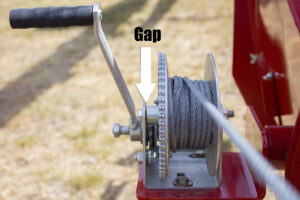
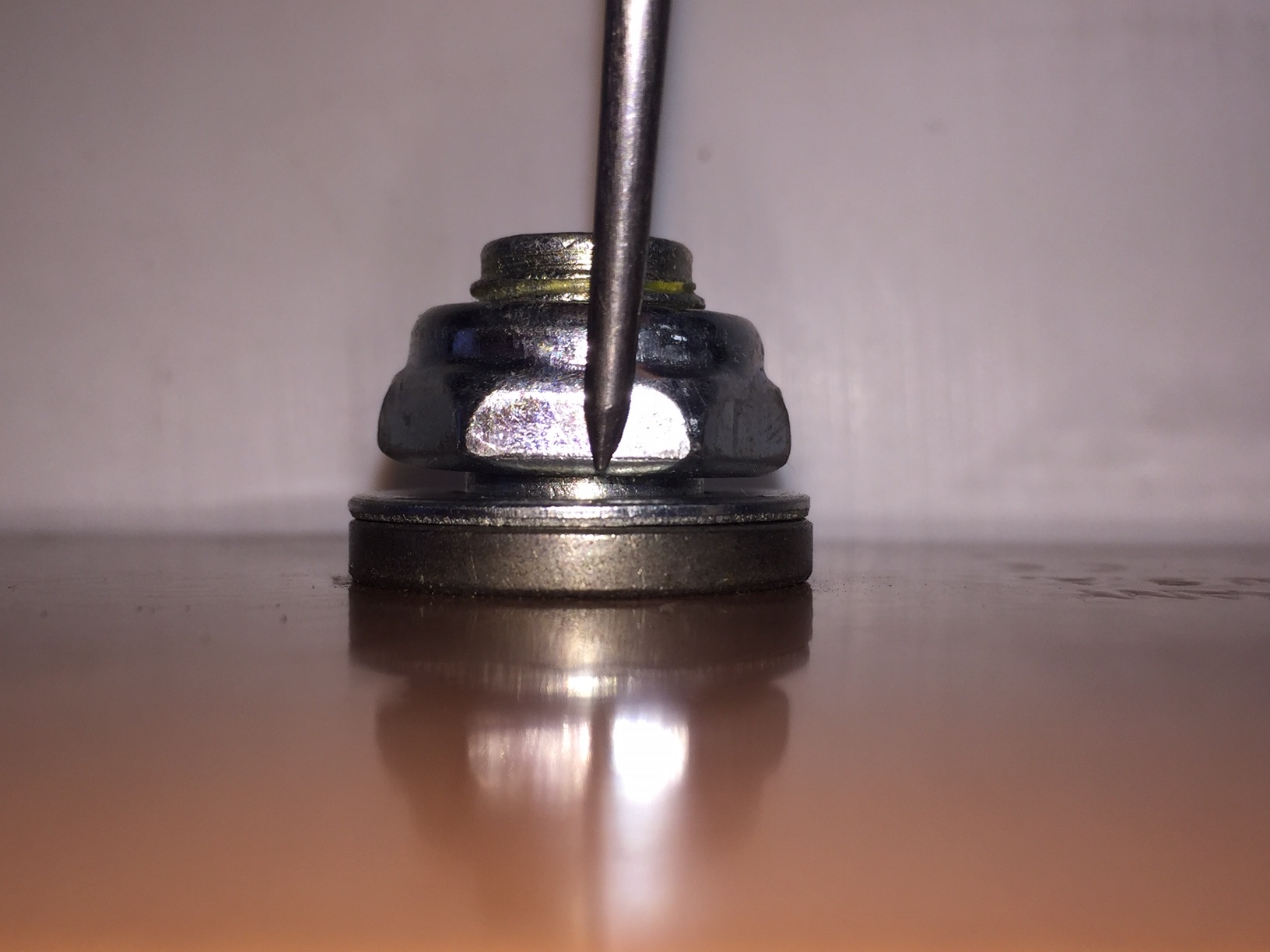
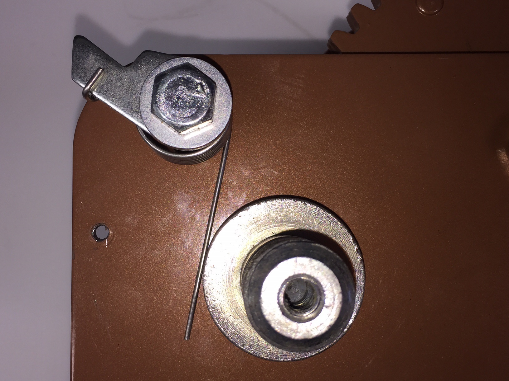
Ensure that your winch’s reel bolt is not overtightened, as this could prevent the reel from turning and your load coming down. There should be a small gap between the reel hub and the base of the winch, as show in the below picture.