Corrective Action:
Make certain that 12 volt power is getting to the switch. If not, check the battery and the connection of the wiring harness to the battery. The most common problem is an insufficient ground connection on the negative wiring harness wire. It is possible to measure 12 volts at the switch with a meter, but have a ground connection that will not allow sufficient current to run the motor. Disconnect and clean the ground connection and reassemble. If the problem is still not solved, check for a faulty circuit breaker by temporarily removing it from the system. Also check the entire length of the wiring harness for a broken wire.
Corrective Action:
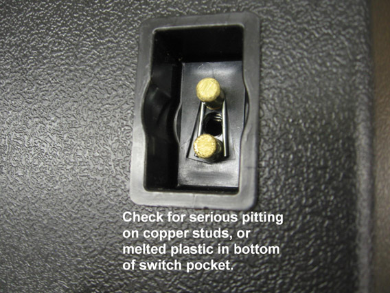
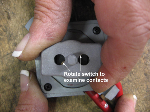
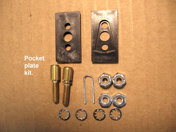
Examine the brass studs in the switch pocket to be sure that they are not excessively pitted or leaning due to melted plastic in the bottom of the pocket. Examine switch for signs of melted plastic or excessive pitting on the contacts. Contacts can be viewed by rotating the rectangular portion of the switch until the edges of the contacts come into view through the two round holes. The contact studs in the pocket of the cover can be replaced with the pocket plate kit 5703129 and the switch can be replaced with kit 5240411.
Corrective Action:
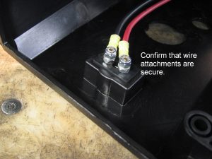
Remove the winch cover and make sure that the motor wires are securely attached to the switch pocket studs and that the nuts are tight.
Corrective Action:
Remove the two motor wires from the brass studs on the inside of the winch cover and touch the wires directly to the terminals of a 12 volt battery. If the motor fails to run, or runs erratically, it needs to be replaced. Order motor 304349.
Corrective Action:
Examine brass studs in the switch pocket to be sure that they are not excessively pitted or leaning due to melted plastic in the bottom of the pocket. Examine switch for signs of melted plastic or excessive pitting on the contacts. Contacts can be viewed by rotating the rectangular portion of the switch until the edges of the contacts come into view through the two round holes. The contact studs in the pocket of the cover can be replaced with the pocket plate kit 5703129 and the switch can be replaced with kit 5240411.
Corrective Action:
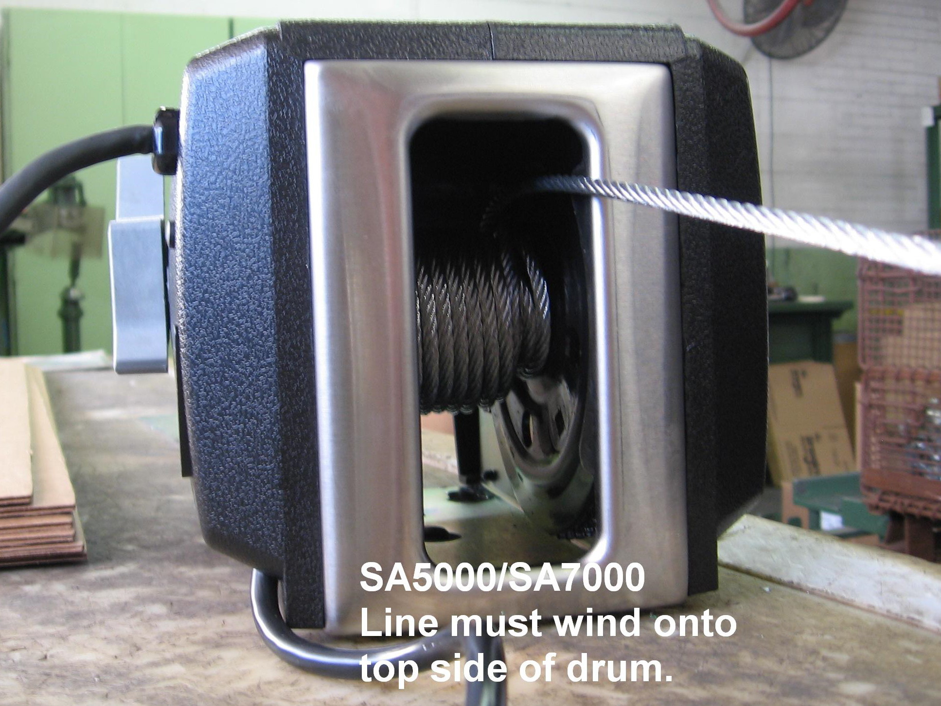
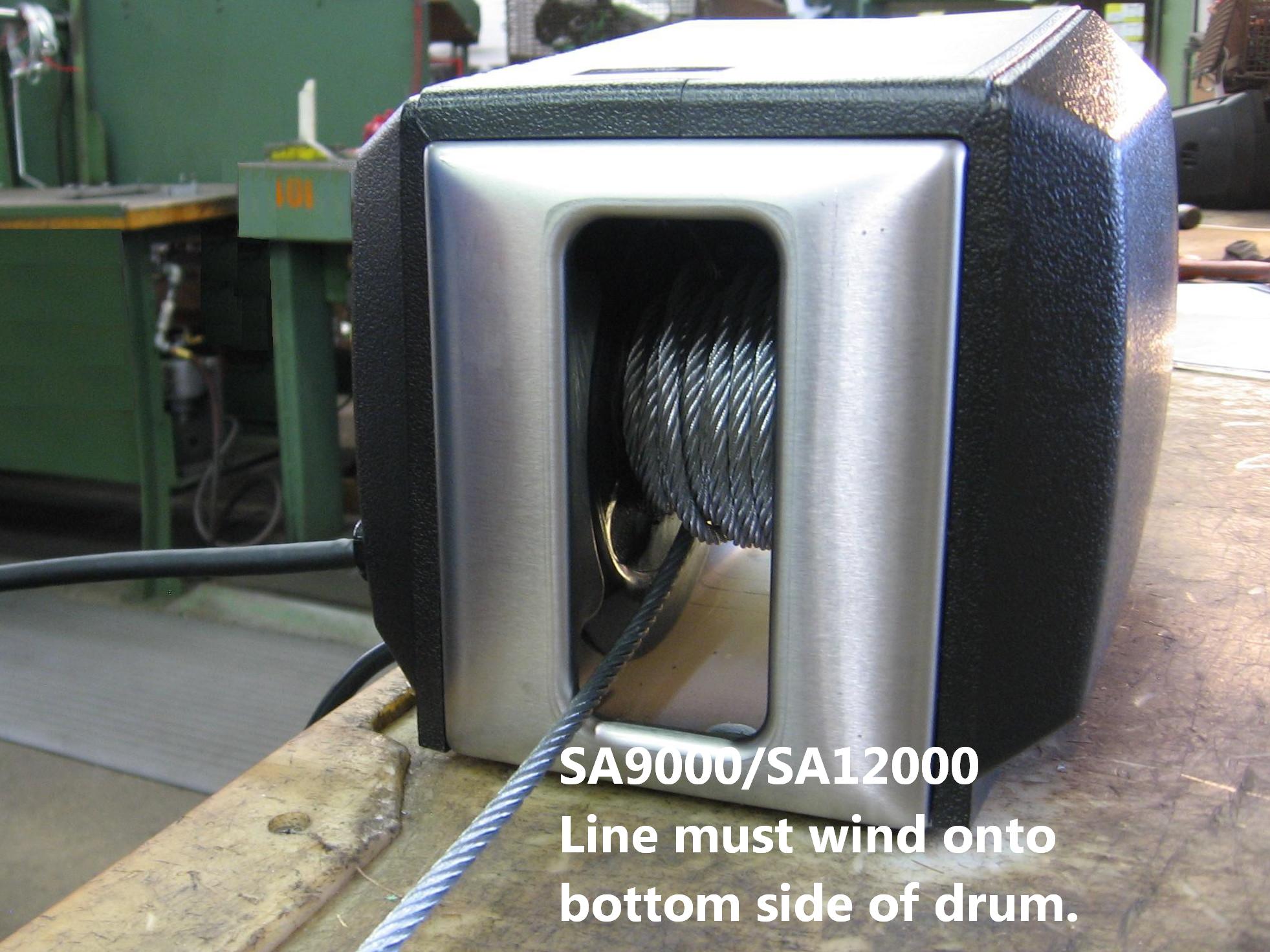
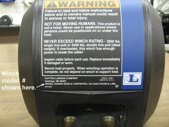
On SA5000/SA7000 models the cable must wind onto the top side of the winch drum and on SA9000/SA12000 models the cable must wind onto the bottom side of the drum. This is critically important and must not be reversed. If you are not sure which model you have, the model number is shown at the bottom of the back decal.
Corrective Action:
Check to be sure the positive harness wire is connected to the positive (+) battery terminal.
Corrective Action:
Check to be sure black motor wire is connected to the top contact stud inside the winch cover. The red wire connects to the bottom stud.
Corrective Action:
If motor slows down a lot and groans to pull load, winch is probably overloaded. Reduce the amount of load being pulled or use a pulley block and hook to increase the pulling capacity of the winch.
Corrective Action:
Recharge or replace battery and confirm good clean connections for both positive (+) and ground (-) wires.
Corrective Action:
On SA5000/SA7000 models the cable must wind onto the top side of the winch drum and on SA9000/SA12000 models the cable must wind onto the bottom side of the drum. If the cable is wound the wrong direction, the motor will be working against the brake and may have difficulty pulling the load. If you are not sure which model you have, the model number is shown at the bottom of the back decal.
Corrective Action:
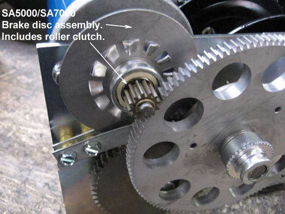
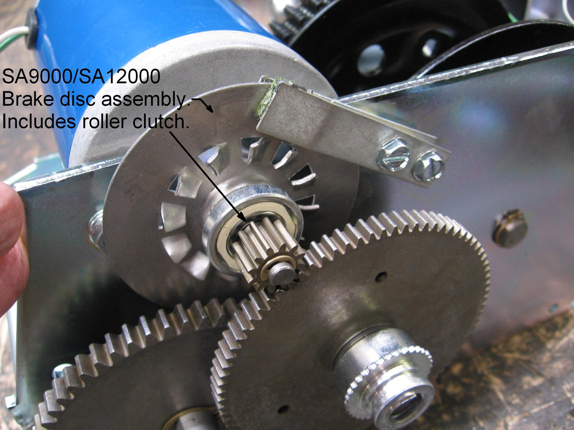
First confirm that cable is wound on winch spool in the correct direction. Then remove the winch cover and observe the brake disc on the motor shaft. If the brake disc spins while the winch is pulling in a load, it needs to be replaced. Order brake disc number 304407 for SA5000/SA7000 models or number 304422 for SA9000/SA12000 models.
Corrective Action:
Move clutch lever to engaged gears position.
Corrective Action:
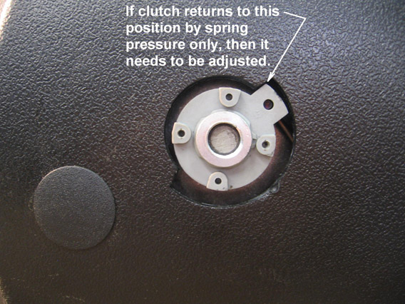
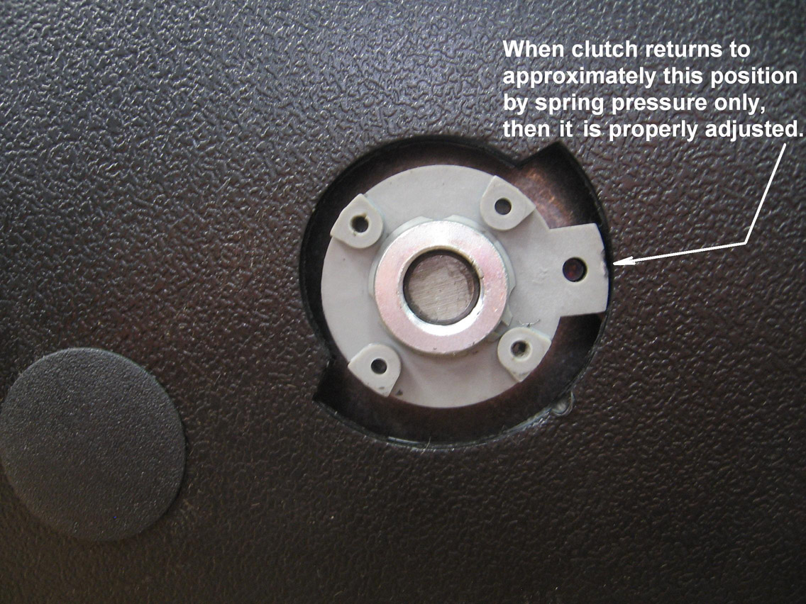
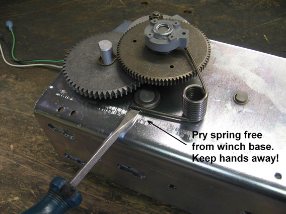
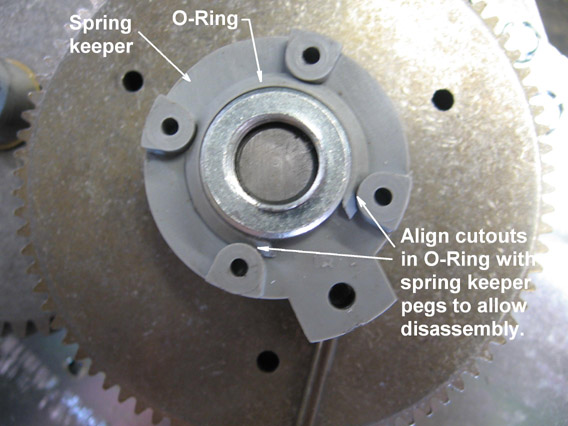
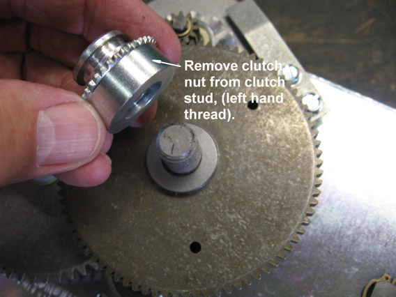
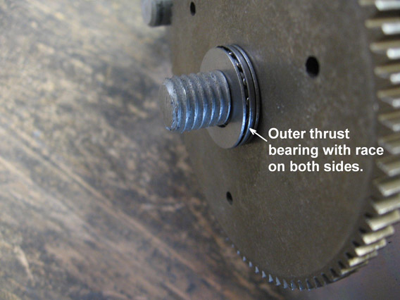
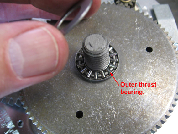
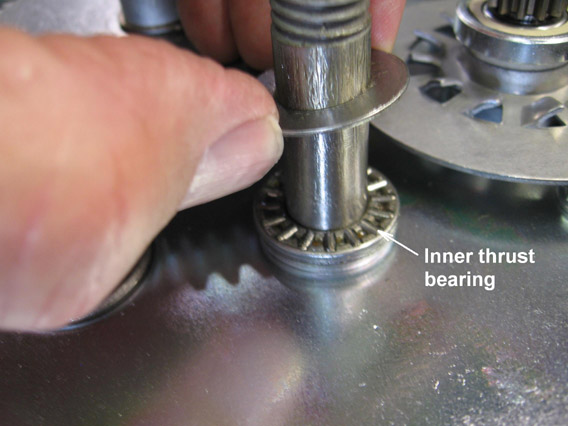
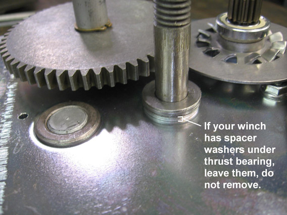
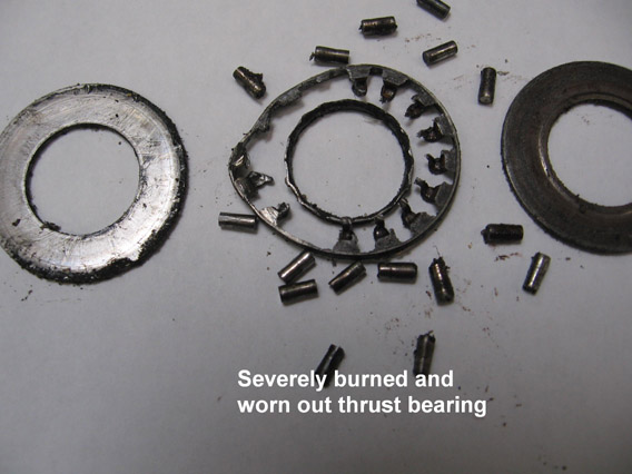
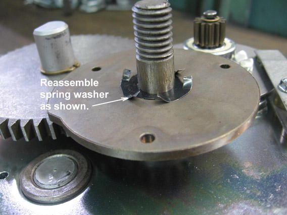
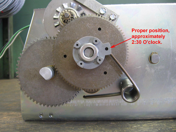
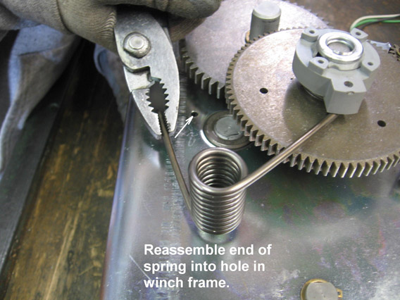
Move clutch lever to freewheel position and then let it gently return to the engaged position using spring pressure only. DO NOT FORCE THE LEVER TO THE STOP. Remove the two small phillips head screws and the clutch lever and examine the position of the spring keeper lug in relation to the stop in the side of the housing. If the lug is touching or very close to the stop (see photo), then clutch is out of adjustment. There are two possible causes which need to be investigated. The thrust bearings could be worn out or the clutch pad could be damaged. To investigate these possibilities, remove the winch cover and disassemble the clutch mechanism as follows. With a flat blade screwdriver pry the end of the clutch spring from the hole in the winch base. The spring tension is quite high and the spring will snap violently when it comes free, so be careful to keep your hands and other body parts away. Rotate the plastic O-ring so the the cut out portions align with the pegs on the spring keeper. The O-ring can then be expanded with a pencil, pocket knife or similar tool and the spring keeper can be lifted free from the clutch nut. Thread the clutch nut off of the stud (it is a left hand thread). You will then see the outer thrust bearing with a hardened bearing race (flat washer) on both sides. Lift both of the gears off of the stud and notice that there is a small spring washer between them. The inner thrust bearing and two races can then be removed. There may be additional spacer washers on the stud and these should remain on the stud. Check the condition of both of the thrust bearings and the races and replace if noticeably worn, dry or burned. Order and install thrust bearing kit 5703194, which includes two bearings and four races. Examine the condition of the clutch pad. This is bonded to the large gear in newer models or bonded to the flange of the small gear in older models. If there are portions of the clutch pad missing or torn away, or any other significant damage to the pad, a replacement is necessary. If the clutch pad in your winch is bonded to the large gear, you can replace just that gear. Order 120 tooth gear assembly 306102 for SA5000/SA7000 models or 84 tooth gear assembly 306101 for SA9000/SA12000 models. If the clutch pad in your winch is bonded to the clutch gear flange it will be necessary to order clutch gear assembly 306100 in addition to one of the above gears. Reassemble and adjust the clutch by the following procedure. Place one of the thrust bearings (with a race on each side) on the clutch stud. Next install the clutch gear and the spring washer oriented as shown in the photo on the stud followed by the large gear turned with the pad facing the clutch gear. Install the outer thrust bearing (with a race on each side) and then install the clutch nut (left hand thread). Use the plastic spring keeper to tighten the nut by hand only. Then insert one leg of the clutch spring into the hole in the spring keeper. Note that on SA5000/SA7000 models the legs of the clutch spring are not equal length. The longer leg attaches to the spring keeper. On SA9000/SA12000 models both legs are the same length and it makes no difference which one attaches to the spring keeper. Position the keeper on the clutch nut so that the lug is positioned at the 2:30 o’clock position (see photo). Reinstall the plastic O-ring and rotate it slightly to lock the spring keeper in place on the clutch nut. Grip the free end of the spring with pliers or vise grips and insert the end into the hole in the winch base. This is challenging because the spring tension is quite high. Make sure the end goes all the way into the hole. Slip the clutch lever onto to the spring keeper and move the lever to the freewheel position and gently allow it to return to the engaged position using the force of the spring only. DO NOT FORCIBLY MOVE THE LEVER PAST WHERE THE SPRING TAKES IT. Remove the lever and check the position of the lug on the spring keeper. It should be at approximately the 2:30 o’clock position (see photo). If not, without moving the position of the clutch nut, disassemble the spring, O-ring and spring keeper and reposition the keeper on the nut so that the lug is at 2:30 o’clock and reassemble. Recheck to confirm that the spring keeper stops in approximately the same position when the lever is moved to freewheel and allowed to return to engaged using spring pressure only. Note that if the lug on the spring keeper is set too high, the clutch may slip under heavy load. If it is set too low the clutch will be too tight and will create excess strain on the motor and excess load and heat on the thrust bearings. Our clutch adjustment video may be helpful.
Corrective Action:
Remove the winch cover. Run the winch and observe which parts are turning and which are not. This should make the source of the problem obvious. Refer to the owner’s manual or website for the necessary repair parts.
Corrective Action:
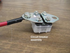
The circuit breaker is designed to cut power to the winch in the event of a substantial overload. It will automatically reset after a short cooling period. Note that the circuit breaker will not protect the motor from damage due to excessive run time.
Corrective Action:
If problem persists after confirming that the load being pulled is within the capacity of the winch, then replace circuit breaker assembly 304025.
Corrective Action:
On SA5000/SA7000 models the cable must wind onto the top side of the winch drum and on SA9000/SA12000 models the cable must wind onto the bottom side of the drum. If the cable is wound the wrong direction, the brake will not work. If you are not sure which model you have, the model number is shown at the bottom of the back decal.
Corrective Action:
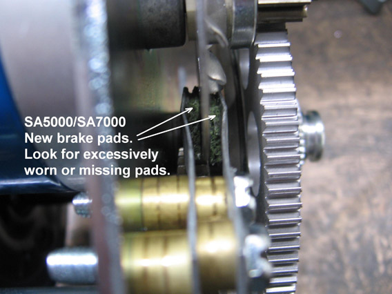
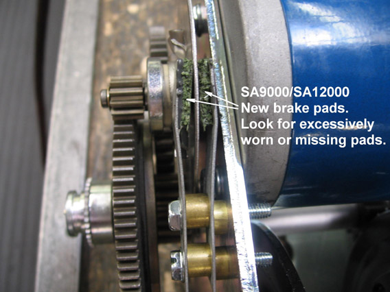
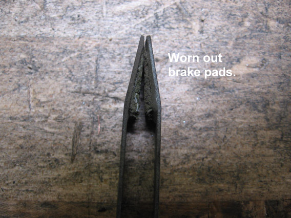
Check condition of the small brake pads that contact the brake disc on the motor shaft. If the pads are severely worn or either pad is missing, order and install a brake spring replacement kit. Kit number 5703186 for SA5000/SA7000 models or kit number 5703160 for SA9000/SA12000 models.
Corrective Action:
Check the operation of the roller clutch in the brake disc. Carefully rotate the brake disc and observe the motor shaft. When the disc is turned clockwise the motor shaft should turn with it. When the disc is turned counterclockwise the motor shaft should not turn. If the operation is not as described, order and install a new brake disc assembly. Order number 304407 for SA5000/SA7000 models or number 304422 for SA9000/SA12000 models.
Corrective Action:
Confirm that load is within capacity of winch.
Corrective Action:
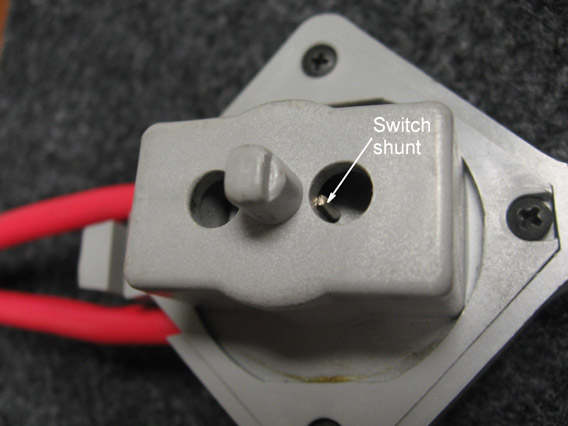
If the winch does not have any difficulty holding the load after it stops, but coasts more than an inch or two before stopping, then the switch shunt may be burned up or not engaging. The winch has two shunts to activate a dynamic brake, one in the switch itself and another is in the bottom of the switch pocket on the side of the winch. The one in the pocket activates the brake when the switch is removed from the winch. The shunt in the switch only makes contact with the studs in the switch pocket when the switch is well centered in the off position. If the switch cannot return to center, the shunt may not activate the dynamic brake. The switch shunt is visible through the holes in the switch (see photo). If it is burned, there is likely other damage to the switch requiring a switch replacement. Order replacement switch kit 5240411. If the shunt in the switch pocket is burned or missing, order pocket plate kit 5703129.
Corrective Action:
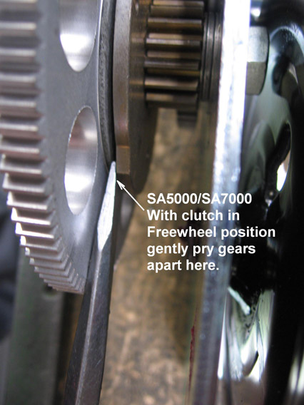
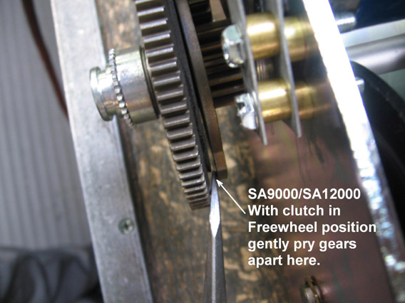
First confirm that clutch is in freewheel position. Then with no load on winch jog power switch to see if clutch will open and allow freewheeling. If this does not work, remove any load from the winch, put the clutch lever in the freewheel position and remove the winch cover. Then gently pry the clutch gear and mating gear apart by inserting a screwdriver between them.
Corrective Action:
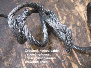
The cable is considered a perishable item and will periodically need to be replaced. Follow these suggestions to maximize cable life: Shorten the cable to the minimum length necessary for your application remembering to keep at least three turns on the drum before starting to pull a load. Excess cable length makes loose, crisscrossing wraps more likely. Make certain that the first layer of cable on the drum is wound neatly and tightly and additional layers will follow in neat, tight wraps. It is essential to keep some tension on the cable during this process. Never start pulling a load with loose cable on the drum. This will almost certainly cause kinks and crushing and wedging cable into lower layers. Allowing loose cable to wind onto drum may also cause it to get caught in gears or other parts causing serious winch damage. It is also important to keep winch reasonably aligned with the load being pulled so that the cable does not severely rub the edges of the cable opening.